2018년 3월 12일 월요일

Electrode Scraper for Electromagnetic Flow Meter for Waste Water

Electromagnetic flow meter is the most favorite flow meter for measuring flow of dirty liquids such as waste water, sludge, slurry, sewage, etc, for its characteristics of not having mechanical parts that can be negatively influenced or damaged by the particles suspended in the dirty liquids.

Having said that, it can't be 100% immune to thickly scaled up deposits on the surface of the electrodes. Such scale built up, if it's of metallic nature, can decrease accuracy or even cause the meter to behave erratically. 

To prevent this, the maintenance engineers at such sites shall perform preventive maintenance periodically to remove such scales built up on the surface of the electrode. First, the pipe must be fully emptied and the flow meter must be removed from the pipe. Then using a metal brush or flat scraper, the scale must be cleanly removed from the surface of the electrode. Then the flow meter shall be installed back on the pipe. As one can imagine, it involves many concerned parties to schedule it and sometimes, it may be necessary to bring heavy equipment if the flow meter is large size. Simply put, it's not a simple task.

The electrode scraping device was developed to make that job simple and easy. Its structure is shown below; 


Because there are 2 electrodes sensing the flow velocity, 2 of these assemblies are attached both on the front and the back side of the flow sensor tube. The electrode scraper assembly has its turn handle exposed outside and lets you turn it thereby scraping the scales off the surface of the electrode inside the pipe.

So, there's no need for emptying the pipe, removing and reinstalling the flow meters.

The followings are the pictures of the actual assembly on the flow meter sensor..


By removing the cap, you can access the turn handle. Turn it several times to remove the scale built up on the electrode inside the pipe.


The electrode scraper on the inside of the pipe.


The handle with the cap on.


Please note that this is not a standard item and is available as an option, and there are limitations as below;

1. The lining must be rubber (which is usually selected for waste water and other dirty liquids).
2. The meter size must be at least 150mm.

To learn more about our MaxiFlo ME series electromagnetic flow meters, please visit our web

2017년 1월 12일 목요일

- Customer: UNICOL Limited


Commission in 2006, Unicol Limited is a joint venture distillery project of Faran Sugar Mills, Mehran Sugar Mills and Mirpurkhas Sugar mills. Unicol's plant is located at Mirpurkhas which is around 230 KM from Karachi. 
Pakistan is presently the 5th largest country in the world in terms of areas under sugar cane cultivation and is consistently ranked in the top 10 sugar producing countries. In the last 2 decades Pakistan has consistently been ranked as one of the 3 largest molasses exporters in the world. However since the new millenium there has been consistent invenstment in ethanol distilling and now the country has become a major ethanol exporter. Ehanol exports have increased from 100,000 tons in 2004 to 225,000 tons in 2010. Record highest exports of 350,000 tons were seen in 2008.
Today there are 15 distilleries operating in Pakistan with an installed capacity of 500 million liters (400,000 tons) and producing different grades of Ethanol. Pakistan has proven itself to produce world quality grades of ENA and ENA Anhydrous ethanol.

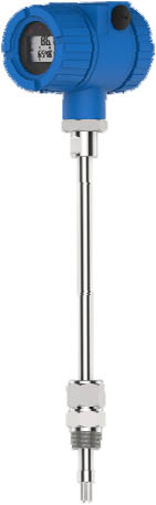
 - Flow Meter Type: MST Series Thermal Mass Flow Meter

  
- Specifications:


Model: MST100-300-I-IC-P2/EX

  - Type: Insertion Sensor with Integral Converter
  - Medium: Biogas (Density: 1.20 Kg/Nm3, Viscosity: 0.018 cP)
  - Meter Size: 12" (300A)
  - Flow Rate: 0 ~ 5000 NM3/H
  - Connection: 1" NPT Compression Fitting
  - Material:
             Sensor - SUS 316
             Wetted Part - SUS 304
             Indicator - Aluminum
  - Operating / Design Pressure: 200 mbarG / 16 barG
  - Operating / Design Temperature: 20~50℃ / 100℃
  - Flow Direction: Free
  - Display: Graphic LCD with backlight (Flow Rate & Total)
  - Input Key: 3 keys
  - Power Supply: 24VDC
  - Output: 4-20mA, Frequency, RS-485 (MODBUS-RTU)
  - Enclosure: IP-65, Ex-Proof (Exd IIC T3)
  - Accuracy: ±1.5% FS ±0.5% RD
  - Repeatibilty: ±0.5% RD

Quantity: 1 Set (This set is being purchased as a trial/evaluation set)


1. Background

The end user, Unicol Limited had decided to replace the existing flow meters (KOBOLD DOG-3 Oscillation Flowmeter) installed in their 16 distilleries in Pakistan. Each distillery needs at least 5 sets. So, the total replacement quantity will be at least 80 sets.

The customer has a biogas production facility that uses spent wash from distillery to generate steam for their distillery process. And the meter will be used for measuring the flow of this biogas, whose typical composition is as below;

Typical composition of biogas
%
CH4
50~60
CO2
40~50
N2
0~10
H2
0~1
H2S
0~3
O2
0~0.5

The reason for that decision is unknown because we supplied this trial/evaluation set through our Pakistani distributor, Process Control Solutions. We don't know how the existing flow meters performed and how long either. They decided to make a big crossover from a by-pass oscillation meter to a thermal mass flow meter. Usually it's not very easy to make such a big changeover. One thing for sure is that they decided to replace them all.
2. Production and Delivery

Because the requirement is very small and didn't require very difficult specifications. But due to the fact that all the thermal mass flow meters have to be calibrated for quite a long time to ensure measurement accuracy. It usually takes 2-3 weeks, which was the case with this meter, too.

3. Installation and Commission
We expect that the customer will be very satisfied with the accuracy and the workmanship as should be authenticated by this trial unit. And we hope that it will lead to customer's satisfaction and purcase of their whole planned replacement meters, which, hopefully will take place in the year of 2017.

End..

2013년 12월 22일 일요일

Dec 2014 --- MVX series Vortex Flow Meters for Korea Nitto Optical (KORENO) Plant in Pyeongtaek, Korea

- Customer: Korea Nitto Optical (KORENO)-

http://www.koreno.com/en/index_en.php


Koreno has been manufacturing the polarizing thin films for TFT LCD since July, 2000. It's a joint venture of Nitto Denko and was chosen as a high-tech company in the foreign companies' complex in Cheonbuk Industrial Complex located in Pyeongtaek City of Kyeonggi-Do, Korea by Korean government. 
                                                                            * Location
165 Cheongbuksandan-ro Cheongbuk-myeon Pyeongtaek-si Gyeonggi-do, South Korea

* Capacity
  - 200 million panel per month
  - Annual Sale $850 million per year
 
* Main Customer
Samsung Electronics Company (SEC)

 - Flow Meters Delivered: MVX Series Vortex Flow Meters and ME Series Electromagnetic Flow Meters

  - Specifications:


Vortex Flow Meter
Model: MVX-040-I-F (1 Set)
           MVX-050-I-F (2 Sets
           MVX-080-I-F (1 Set)
           MVX-100-I-F (3 Sets)
 
  - Fluid: Saturated Steam (Density: 7.128 Kg/m3)
  - Flow Rates: From 1200 to 7000 Kg/h (Span)
  - Connection: JIS 10K Flanges
  - Material:
         Body & Flange - SUS 316 & SUS 304
         Indicator - Cast Aluminum
  - Oper'/Design Pressure: 10 barg  / 16 barG
  - Oper'/Design Temperature:  194.279℃ / 350℃
  - Flow Direction: Right to LeftBOT -TOP
  - Power: 24VDC
  - Output: Pulse
  - Accuracy: ± 1%, Reading 
Quantity: 7 Sets 

1. Background

The end user, Korea Nitto Optical (KORENO), is currently expanding their production capacity by building a new plant besides the existing plant over three phases. The facility our meters were delivered to and installed for was built as part of the 1st phase. And the contract for this phase was awarded to POSCO Engineering Co., Ltd. And the part of the contract where the system for heating control and the waste water control shall be built was subcontracted to Kukje Building Management System Co., Ltd.

Kukje BMS then selected our MaxiFlo MVX series vortex flow meters and ME series electromagnetic flow meters to measure and control the flows of steam and waste water.

2. Production and Delivery

A total of 7 vortex flow meters of varying sizes from 40mm to 100mm for measuring saturated steam and 3 electromagnetic flow meters of 100m (together with a batch controller for each electromagnetic flow meter) for measuring waste water were ordered in the middle of September 2013. And they were all delivered in time (20 days after receiving the downpayment) and were installed by Kukje BMS site engineers.

All the meters were set up and calibrated according to the order specifications and therefore, all the installing engineers had to do was to insert the meters between the flanges of pipes according to the flow directions, tighten the flange bolts, connect the powers and output cables, and up they went. Oh, not quite.

3. Troubles and Sorting Them Out

About 1 month had passed since we had delivered the meters and received all the payment, when the site manager of Kukje BMS called us up and said that they suspected that the electromagnetic flow meters were not giving pulse outputs to the batch controllers (we delivered these, too, as a package) and asked us to visit the site and solve the problem.

After checking everying was done correctly as was supposed to over the phone, I decided to pay a visit to the site rather to be just nice than to look into what was really going on, because I was sure that some very simple thing was missing and it could be sorted out in minutes.

At the site, I checked first the indicators of the 3 batch controllers that were supposed to receive output pulse signals from the electromagnetic flow meters to see that one was showing value and the other 2 did not register any values. It later turned out that the other 2 were not wired correctly. They had connected the cables to 4-20mA output instead of the pulse output terminals. So, there were no problem with the electromagnetic flow meters or with the batch controllers, exactly as I had envisioned. Further the site engineers confirmed that all the elctromagnetic flow meters were showing accurate flows and the batch controllers were acting as they were supposed to,i.e., starting the pumps and stopping them when the batch is full.

And then the site engineer casually said that they were not receiving any pulses from the vortex flow meters. So, I went, "What? Why didn't you tell me about it before? I could have been better prepared, had I known that there were such problem with the vortex flow meters." I was not upset but was quite alerted becase I didn't expect this even in my wildest dream because they have kept silence about it for such a long time after installation. Anyways, we went upstairs where the vortex flow meters for steam were installed.

Pipings of steam were all installed at elevated locations close to the ceiling and the walls. I guessed it was to save the plant space and for safety reasons because steam pipes are very hot usually over 200 degrees. And therefore it was extremely difficult and dangerous to climb up and get access to where the meters were installed. One site engineer went up and shouted that the indicators were all dead and there were no signs of the meter working. "That's really strange.", I thought. So, I climbed up and confirmed that it was actually true was really surprised. I measured the supply voltage with a multimeter and confirmed that the power was 24VDC and was correct. Then I moved to the next one and repeated the same thing. In doing so, I found one indicator was severely damaged by a burn. I stopped the work because it was too late close to the off-duty hour. I showed the burnt indicator to the site manager, explained to him that possibly a user's mistake of applying 220VAC could have been the cause of all the problems and suggested him that I would come back with a new one to replace this burnt one. But for the other ones, I didn't have any clue whatsoever that might be causing the problem. So, I thought it better to start from the beginning step by step with the new set and try to see what differences can there be. When I came back to the office, I took a photo of the burnt boards as below. It's literaly scorched.


When I visited the site again with the new indicator, it powered on ok. At this point I got more confused. Why wouldn't the other ones power on? I decided to test the other ones by replacing the circuit boards with those of new one. I first opened the back cover of the indicator to expose the terminal strips and the circuit boards of another one. I loosened the 3 screws and at that moment, one of the site engineers who was watching what I was doing said that the indicator powered on, and then off again. What happened was that when the circuit board touched the indicator chassis, which is connected to the sensor body, then to the pipe and then finally to ground, the indicator turned off, but when the circuit board was lifted away and not touching the chassis, it powered on, even though it was not showing any flow rate, while it should. I could worry about the flow reading later. What was important was to have all the meters power on first.

Now, I made a progress to finding the cause of the problem. But why was it happening? What happened to the circuits? 


I concluded that all the meters were damaged in their internal circuit because the installing engineers first applied 220VAC by mistake.

So, I explained to this to the site manager and told them that all the circuit boards had to be replaced. The site manager agreed and we removed all the indicators and took them back to our facility.

Back at our facility, we tested each board from the site by applying power, and then having it connected and disconnected to the building's ground. It confirmed that the situation at the site was replicated at our facility. We then took new boards and repeated the same test but what happened with the boards from the site didn't happen with the new boards. At this point I conferred with confidence that they applied wrong power (not necessarily 220VAC because there were 24 VAC instead of 24VDC, too.).

On the 3rd visit, I started reinstalling the indicators from a big pipe (100mm). It powered on ok and to my great relief, it showed the flow rate value. So, I shouted to myself, "Yeah, way to go". Then did the rest of the meters at the same place one by one. As a result, 2 100mm pipes showed values, 80mm, on and off and 50mm, none. When I finished replacing the indicators of the 4 meters, it was already late. So, I called it a day and decided to come back the next day.


On the 4th visit, I replaced the remaining 3 sets. The result was that 100mm showed flow rate but 50mm and 40mm didn't show the flow rates. But I confirmed that there were no error with the indicator and the sensor by observing the indicator while kicking on the pipe near the sensor. When I did, the indicator showed value briefly because the vibration of the pipe increased the impact of vortices sensed by the detector.

Now, I declared that the work was finished and complete, and that successfully. In summary, all 4 meters on big pipes (100mm and 80mm) showed the flow rates, but the other 3 meters on small pipes (50mm and 40mm) didn't show flow rates. Given the results, the site manager confirmed that the valves were not fully open, the system was designed to host the eventual demand when the plant was finished over 3 phases. So, the system was running at 1/3 of it's designed capacity. Therefore he agreed that the flow rates of the smaller pipes are below the minium flow velocity requirement of 4 m/s. So, I asked him to open the valves just for test purpose to establish that the other flow meters for smaller pipes were actually ok. But he said that he had no authority to do it and was satisfied with the result in hand.

He then asked to see the pulse signals coming from the meters to PLC distribution panel. So, I took the pulse counter and connected to several meters that were showing the values and in came the signals. Bingo! Job done.

4. Epilogue

As one can see, from the beginning, there were no problem with the 7 sets of our MVX series vortex flow meters delivered. The site engineers mistakenly hooked up 24 VAC instead of 24VDC and burnt up the circuits of the indicators, which they indirectly admitted. They said if it was actually true, then they could claim the damages on the PLC subcontractor who designed the power supply for the meters.

I personally paid 4 visits to the site because all our engineers were out installing the ultrasonic flow meters at other sites. And I was the only one available and with required knowledge (though I admit it's not that sufficient). I had cuts and bruises during the work. I had to replace 8 circuitboards entirely. And that cost was very high.

But I didn't mentioned any of it to the site manager. My only focus was on solving the problem and getting the hands-on experience with vortex flow meters and steam because we have little experience with them both. And it was quite an experience and good and resourceful experience.

After the job was finished, I searched the internet for some knowledges about steam and this is what I first found. You can enjoy them, too.


Goods places to learn about Steam
.TLV

 End

2013년 6월 28일 금요일

Apr 2013 --- KM series Metal Tube Roatmers and MT series Turbine Flow Meters delivered to Shurtan Gas Chemical Complex (SGCC) of Uzbekistan

- Customer: SHURTAN GAS CHEMICAL COMPLEX


SGCC is Unitary Branch Establishment of the Joint Stock Company “Uzneftegazdobycha” of the National Holding Company “Uzbekneftegas”. In 2005 was successfully certified acting Quality Management System by certification center TÜV CERT in accordance with requirements of ISO 9001:2000.

* Location
Shurtan Gas Chemical Complex is situated in the south-west of Uzbekistan (Kashkadarya region, Guzar district), in the desert area of the Karshi steppe and constructed on the basis of Shurtan gas condensate fields.

* Capacity
  - Natural gas processing 3.9 milliard m3/year.
  - Pure methane output 3.5 milliard m3/year
  - PE granules 125 ktpa
  - LPG 100 ktpa
  - Gas condensate 100 ktpa
  - Granulated sulfur 1.5 ktpa

* Finished Products
Starting from 2006 we produced finished products in the form of pressure pipes and fittings for pressure pipes by reprocessing more than 5 thousand ton/year of polyethylene. And now this figure reached 10 thousand tons per year after launching production of aluminium composite panels and components of drip irrigation systems.

 - Flow Meters Delivered: KM Series Metal Tube Rotameters and MT Series Turbine Flow Meters


  - Specifications:


Metal Tube Rotameter
Model: KMFA-1-B
 
  - Fluid: Water (Density: 1000 Kg/m3, Viscosity: 1.0 cP)
  - Flow Rate: 0 (400) ~ 4000 Kg/h
  - Connection: ANSI 600# 2" RF
  - Material:
         Body & Flange - SUS 304 & SSC 13
         Indicator - Cast Aluminum
         Float - SUS 304
         Taper Tube - SUS 304
  - Oper'/Design Pressure: 4400 kPaG  / 40 barG
  - Oper'/Design Temperature:  270℃ / 360℃
  - Flow Direction: BOT -TOP
  - Length: 250 mm (Face to Face)
  - Accuracy: ± 2% F.S
  - c/w 2 Sets of Spare Floats
Quantity: 6 Sets 


Turbine Flow Meter
Model: MTL-150-T4-G-P1-F2-AN
 
 
- Fluid: Liquid
  - Flow Rate: 0 (40) ~ 400 M3/H 
  - Connection: ANSI 150# 6" RF
  - Material:
         Body - Stainless Steel
         Rotor - ANC1A Stainless Steel
         Rotor Shaft - Tungsten Carbide
         Indicator Case - Aluminum
  - Operating / Design Pressure: 8 barg / 10 barg
  - Operating / Design Temperature: TBD / 120℃
  - Flow Direction: Single Direction
  - Length: 300 mm (Face To Face)
  - Output: 4-20mA (Source Powered)
  - Power Supply: 24VDC
  - Display: 2-Line LCD (Flow Rate-4 digits, Total-8 digits)
  - Pressure Loss: 0.025 Mpa
  - Accuracy: ± 1%
  - Linearity: ± 1%
  - Repeatability: ± 0.3%  
Quantity: 4 Sets 


1. Background

The customer, Shurtan Gas Chemical Complex (SGCC), started procurement process from the end of 2012, where we submitted our first quotation. After reviewing our technical and commercial proposal, they came back with contract draft in April 2013. After several exchanges of drafts and corrections, we signed the final contract and submitted it to the customer.

Then another entity came into play. They were  UZConsulting, which is a government agency and, as a standard procedure, does a price auditing for major international procurements of government organizations. What they did was, after they receive a procurement proposal from many of Uzbekistani government organization, they verify whether the price to be contracted is fair or not. As part of it, they send inquiries under their name to all the manufacturers and suppliers of the world, as if they are the actual buyer. And if they receive prices under the prices that they already have, then they ask the government agency to negotiate the price down.

Because SGCC promises to be a solid customer with a lot of potential of follow-on orders, we decided to take the contract after giving them about 30% discount from the original contract amount. And I don't have any regret about that.


2. Production and Delivery


The required specifications for metal tube rotameters was not very easy because some of them should operate under 40 barG max. pressure. Additional precautions were needed to ensure this. And because we had a lot of production going on at that time, the delivery was a little bit delayed.

3. Acceptance and Certification at the Customer

We learned that all the flow meters for the government agencies in Uzbekistan are subject to certification by Uzstandard. Without passing this certification process, the flow meters cannot be put into use.

And then there was a problem. The contract required 2% FS accuracy for metal tube rotameters, while our standard accuracy is 2.5% FS for gases. This is not a problem because even though we say 2% or 2.5%, we always calibrate our rotameters to 1% FS accuracy. The problem was that our worker who issues test and calibration certificate didn't pay much attention to the product data sheet and issued the certificates with 2.5% FS standard accuracy.

So, we reissued the certificates at the customer's request. And they all passed the certification process of Uzstandard.

4. Acceptance and Certification at the Customer


SGCC is our first customer in Uzbekistan and they are a very important customer. And with the successful delivery of the meters, we hope that our brand, MaxiFlo, will find more customers in this country.

End..


2013년 1월 27일 일요일

Dec 2012 --- MaxiFlo KOI series delivered to National Refinery Limited (NRL), Pakistan

- Customer: National Refinery Limited Pakistan


NRL is engaged in the manufacturing. Production and sale of large range of petroleum products. The refinery complex of the Company comprises of three refineries, consisting of two lube refineries and one fuel refinery. First Lube Refinery commissioned in 1966 with designed capacity of 539,700 tons per annum of Crude Processing and 76,200 tones per annum of Lube Base Oils. Second Lube Refinery commissioned in 1985 with designed capacity of 100,000 tons per annum of Lube Base Oils.
The Fuel Refinery commissioned in 1977 with designed capacity of 1,500,800 tones per annum of Crude processing and after revamp the designed capacity comes to 2,170,800 tones per annum of Crude processing. 
The BTX unit was commissioned in 1985 with design capacity of 25,000 tons per annum of BTX.
NRL enjoys a competitive edge, as it is the only refinery producing LBO in Pakistan.

 - Flow Meter Type: KOI Series Panel-Mount Purge Meter

  - Specifications:


Model: KOI-A-1
 
  - Fluid: Air (Density: 1.293 Kg/m3, Viscosity: 0.018 cP)
  - Flow Rate: 0 (200) ~ 2000 Ncc/min
  - Connection: NPT 1/4"" (Female)
  - Material:
             Body - SUS 304
             Tube - Pyrex Glass
             Packing - N.B.R
             Needle Valve - SUS 304
             Cover - Acrylic
             Float - MFR STD
  - Operating/Design Pressure: 60 psiG / 10 barG
  - Operating/Design Temperature: 20℃ / 100℃
  - Flow Direction: Bottom Rear - Top Rear
  - Length:: 130 mm (C to C)
  - Accuracy:  ± 2.5%, F.S
  - With Needle Valve at the Inlet

Quantity: 2 Sets 


1. Background

The customer, National Refinery Limited (NRL), Pakistan had put the purchase of the 2 sets of purge meters on a tender in May 2011. We submitted our bid. But the customer cancel the bid for some reason that we don't know. It put the same procurement on a tender again in November of 2012 and were were selected as the supplier for this requirement.

2. Production and Delivery

Because the requirement is very small and didn't require very difficult specifications, it took only about 5 days to produce and have them ready for delivery.

3. Installation and Commission
We expect that the customer will be very satisfied with the accuracy and the workmanship to be authenticated by these purge meters. And we hope that this first experience of our rotameters will lead to customer's satisfaction and more and larger projects in the future.

End..

2013년 1월 22일 화요일

Nov 2012 --- MaxiFlo - KM Series Metal Tube Variable Area Flow Meter (Rotameter) to be delivered to Total Group

- Customer: Total E&P (Exploration and Production) UK


TOTAL E&P UK Limited is one of the largest operators in the UK sector of the North Sea in terms of production and reserves, and is one of the largest exploration and production subsidiaries of the TOTAL Group.

 - Flow Meter Type: KM Series Metal Tube Rotameter

 
- Specifications:


Model: KMFE-2-A

  - Fluid: Natural Gas (M.W: 19.7, 0.018 cP)
  - Flow Rate: 100 ~ 800 NM3/H
  - Connection: ANSI 600#  1" RTJ Flange
  - Material:
         Body & Flange - Carbon Steel & SS 400
         Indicator - SUS 304 (Magnetic Coupling Type)
         Float - SUS 316
         Taper Tube - SUS 316
  - Oper'/Design Pressure: 44.22 barg  / 55.2 barg
  - Oper'/Design Temperature:  25℃ / 120℃
  - Flow Direction: BOT -TOP SIDE
  - Length: 325 mm (L) x 100mm (N)
  - Accuracy: ± 2.5% F.S

Quantity: 2 Sets (2 Sets were added in the beginning of January 2013)


1. Background

The customer, Operation and Maintenance Team of Total E&P, UK was seeking  rotamaters to replace their existing models (Brooks) because these models were not available from the original manufacturer. After searching the internet and other sources, they found our model KMFE and were certain that our model could replace their existing ones.

They sent us an inquiry for 2 sets. And after numerous exchanges of questions and answers and after submitting relevant technical data with drawings, we succeeded in wining the purchase order, which was given to us by the customer's purchasing agent in UK.

We believe our track record of high-performance metal tube rotameters (compatibility with high pressure, high temperature, highly corrosive environment, hazardous environment, etc.) in the field of Oil & Gas Exploration and Production especially in Middle-East (Rashadat, South Pars, etc.) area should have help position us in the better place in winning this order.


2. Production and Delivery

Because of the characteristics of oil exploration and production, the required specifications are usually very high. The oil has to be pumped up to the production platform from hundreds or thousands of meters underground. Therefore the pipe pressure is usually very high. And because production platforms are located offshore, high anti-corrosive material against sea environment is required.

So, we paid a lot of attention to make the meter to withstand the high pressure by adding more mass to the materials and applying anti-corrosion paints.

But the delivery was a little bit delayed (eventually about 2 weeks) because we had to have the RTJ flanges made from outside. (We usually machine European standard or high-pressure rating flanges for ourselves. But because RTJ flanges require much more accuracy than other flanges, we decided to purchase them from outside.)

3. Installation and Commission

After receiving the meters or more precisely before the arrival of the meters, the customer realized that the meter size ordered was actually wrong. So, they increased the size to 1-1/2" from 1" and placed another PO for the new size.

So, as of this moment, late January of 2013, the meters delivered haven't been installed and will never be because they will be replaced again by the new sizes.

End..


2011년 3월 18일 금요일

MaxiFlo Application Note - MST Thermal Mass Flow Meter installed in Pars Khodro of Iran

- Customer: Pars Khodro, The Automobile Maker of Tehran, Iran
- Series: MST200
- Indicator: Remote Type
- Sensor: Insertion Type
- Quantity: 38 sets (11 for Compressed Air and 27 for Natural Gas Lines)
- Period of Installation and Commissioning: 5 days from Feb 15 to 20, 2011

- No. of Engineers from MaxiFlo: 2

1. Background

The customer, Pars Khodro is the 3rd largest automobile manufacturer of Iran. It is the first to start manufacturing cars in Iran and is currently assembling 1,200 cars under license of Pride of Kia, Nissan, Peugeot, etc. About 7000 employees are working around the clock 7 days a week. The factory sits on a large estate in the automotive industrial complex on the outskirt of Tehran.

Iran has a vast reservoir of natural resources such as oil and natural gas. They are the world's second largest exporter of natural gas after Russia. Until recently, Iran, as a nation, didn't pay much attention to saving or efficient use of their natural resources. But recent hike in oil and gas prices changed that.

Pars Khodro which is a state-owned company became the first to enforce such change of the nation's attidude towards saving of natural resource. They wanted to start it by accurately measuring their natural gas and compressed air consumptions. For the inital phase, they selected the 38 spots to measure and searched for the sources of flow meters.

But there were limitations. They are that the meters must be installed on existing pipes and that the pipe cannot be closed for sensor installation because the car manufacturing line must be up and running 24 hours a day. The only viable options left were insertion type thermal mass flow meter and the insertion type turbine meter. The turbine type was ruled out because it's mechanical nature gave cause to concern about the explosion for the natural gas line. Of course, turbne types have many disadvantages when compared to thermal mass flow meters, one of them being narrow turndown ratio of 10:1. Thermal mass flow meter's turndown ratio is 100:1 at least. The customer started looking for the suppliers of thermal mass flow meters from all over the world from May 2010. Of course, there are many famous brands such as Kurtz, Fox, Sierra, etc. I don't know whether all of them bid for this project but 2 companies Binder Group of Germany and us, Seil Enterprise Co., Ltd. of Korea were downselected eventually.

The customer fine-tuned the specifications with these 2 companies until the last stage and we ended up wining the contract for the supply, installation and commissioning of 38 sets with our thermal mass flow meter series MST200. I believe our winning points were our good price, versatile interfaces and short delivery.

We delivered a little behind the schedule because there were many upgrade of software 38 sets of model MST200-###-D2-IC-P1-C100 (Remote type with insertion sensor with compression fitting, 220VAC power and 100m sensor cable). The main components, indicator, sensor and the compression fitting as shown as below;


Indicator


Sensor


Compression Fitting


2. Site Condition

I and one of my staff engineers (my brother) flew to the customer's automobile factory in Tehran to install and commission the 38 sets of our MST200 series thermal mass flow meters. Our mission was only to install the insertion sensors and the remote indicators. And putting the sensor cables inside the cable hose and laying the hose between the indicators and the sensors were the job of our local agent and site engineers.

The most of the sensor and the indicator installation spots were outdoors. The pipe sizes ranged from 3" to 12". Where the sensors were to be installed were welded with ball valves, through which the insertion sensor is inserted and fixed. The internal pressures of the pipes were from 3 barg to 7 barg, with those of compressed air a bit higher. Weather-proof boxes were prepared, so that the indicators can be housed inside.

So, the installation task was simple. Insert the sensor on the ball valves, put the indicator inside the weather-proof box and connect the sensor cable to the indicator.

But it was not so simple. When inserting the sensor through the ball valve, we had to open the ball valve, insert the sensor and quickly tighten the nuts of the compression fitting. If the pipe was not pressurized, it could have been done by one person. But because it was pressured with up to 7 barg, we needed 3 persons at least. One to insert the sensor and hold it in position, one to open the valve and hold the valve to stop from turning and the last one to tighten the 2 compression fitting nuts. Because the locations were mostly elevated above the ground by about 5 - 7 meters, it was extremely difficult and dangerous because there was no platform provided. Each person has to use both hands and somehow hold himself, so that he won't fall.

The air and natural gas escaping through the space between the sensor and the valve opening made horrific hiss and it was not at all to hold the sensor from popping out due to the pressure. Air was ok but the natural gas was a totally different thing because they are flammable or explosive. Before we left for Iran, we asked the customer to empty the natural gas lines by purging with inert gas for the safety concern. But the customer couldn't accept it because they cannot stop the production line. At first, the pure though of inserting metallic sensor on the metal pipe (sparks can occur when they collide each other.) sent me chill through my backbone. But I could overcome it and finally got confidence that with a little precaution, that the accident can be avoided. In reality, the gas will be released into the open atmosphere and therefore the gas will quickly get diluted and become very thin. So, if there's no immediate and direct source of fire, the possibility of fire or explosion was very low.

Anyways, it was a good idea to do compressed air lines first. That way we could get the feeling of the pressure and other environment before we do the dangerous gas lines. When we started the first gas line, it was a bit scarry but after this first one, the gas lines were no different from air lines.

The pictures below are for the first 3 sets installed on compressed air lines.

Sensors have been inserted through the ball valves.

The indicators have been put inside the weather-proof boxes.


The sensor has been installed on vertical natural gas pipe outdoors.

Our job was to install the indicators and the sensors. If we did only that then we could have finished the job in just 3 days. But the reality is always not the same as the plan. The job of putting the sensor cable into the cable hose and laying the hose from the indicators to the sensors was supposed to be done by the helping hands of our agent. And the all the toos needed must have been prepared, even though we brought our tools. But there were no tools that had been prepared by our agent or by the site engineers. We had to use only the tools we brought. So, even though there were many people (some working and some just looking), the work was not as fast as we expected, because there was not enough tools. There was always outcries for tools. "Give me the driver!" "Where's the scissors?".... for the whole length of 5 days of work.

Also, the flow meters must have been in place ready to be installed. But that didn't happen either. After one site was finished, we moved to another site. We naturally expect the meters to be there but there was none. So, the site engineer had to drove back to the center and bring it. Then we had to waste for about 30 minutes. Sometimes longer.

The people there were very kind and friendly. When we were busy doing the job out in the cold, one of site engineers used to bring hot kettle of 'Chai', Iranian tea, which was really good and sugar. The tea was really really good and even the sugar. (I bought 5 boxes of this tea at the airport on my way back. It was cheap.). And they were very curious about us, Asians. Wherever we go, the crowds shouted "Niha", "Are you Chinese?", "Hello!"..... Then we say, "We are Koreans.". Then oh, "Park, Jisung!!!" (the famous Koren soccer player of Manchester United.). Also, some popular Korean TV drama figure names such as Jumong, Soseono, Daejangeum, ..... And also the people outside factory was really nice.  We went to a regular restaurant outside hotel and they wanted to take pictures with us.

A picture at a restaurant outside hotel

A shot after one site is finished. (I recorded the flow readings for later)


The staff of our agent (Mr. Hossein Kohi) wanted a shot, too.


3. Result of the Work

Though there was some difficulties such as shortage of the tools. We could finish the job in time. Our agent's bringing 2 more helping hands on the last day of the work helped a lot.

The site engineers monitored the flow rate readings of the meters that had been installed.  And they said that the meter readings were generally lower than they had expected.  I did a presentation on the principle of thermal mass flow meter and explained the difference between the flow rate units of Normal cubic meter per hour (Nm3/h), actual cubic meter per hour (m3/h), standard cubic meter per hour (Sm3/h) and kilogram per hour (Kg/h). They all understood them and realized that our meters were correct. And they gave us thums-up.

4. Future Plan

The 38 sets we installed were for the first phase of the program. The customer has a plan to do the 2nd phase soon and about an equal number of the meters will be required. And they want to tie all of them to a central monitor through network. And we hope that we can build the central monitoring system using our software and networking technology. 

5. The Advantages of Thermal Mass Flow Meter

- Thermal mass flow meters are pure solid-state flow meters as opposed to legacy mechanical counterparts such as orifice, rotameter, turbine meters, etc. So, there's less point of failure due to wear and damage.

- With the insertion sensor, the price of the meter won't increase for the increased sizes of the pipes.

- Also with the insertion sensor, you don't have to stop the line for the installation of the sensors. (Of course, you have to stop the line to weld the ball valves. But this can be carefully planned for regular maintenance in advance.)

- The mass flow is measured directly. You don't need pressure or temperature inputs as is the case with orifice types or turbine types.)

- Because the meter is on the electronics basis by definition, it offers versatile output options such as pulse, 4-20mA, alarm, RS-485, etc.

- For more information, you can download the catalog of our MST series thermal mass flow meters from our web, www.maxiflo.co.kr/Cat-Manual/Catalog_ThermalMass.pdf.


This was written by Suh, Sukho of Seil Enterprise Co. (405 Halla Sigma Valley 345-90 Gasan-Dong Geumcheon-Gu Seoul Korea)